
Session 7 — Hello, Hardware!
Duration: 75 min · Format: live online
What you'll learn: by the end, you can explain the Sense → Think → Act loop, build an LED circuit in a simulator, and write Arduino code that makes it blink.
Soft skill focus — Problem-solving
Today you'll also grow Problem-solving. A dead LED has only a few possible causes — an incomplete loop, a missing resistor, or a backwards LED — and finding it means checking them one at a time, not guessing wildly.
- Try this: when your LED won't light, don't guess randomly — trace the circuit as a single loop (pin → resistor → LED → GND) and rule out one suspect at a time until you isolate the fault.
- Think about: when your circuit didn't work, how did you narrow down where the problem was?
What you'll need
- A Tinkercad Circuits account, signed in and ready to Create new Circuit — no hardware needed, you'll build and simulate everything in your browser.
Hook
Think about this question:
- "How does an automatic door know when to open?"
Here's the pattern: it senses you, decides to open, and acts by moving. Almost every smart device works this way — and today you build the smallest version: an Arduino that makes a light blink.
Teach — Sense → Think → Act
A tiny computer called an Arduino connects code to the physical world through a three-step loop.
Look at this diagram:
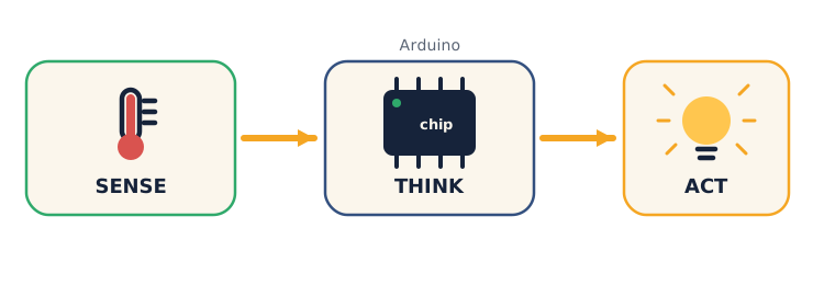
- Sense — inputs (a button, a light or temperature sensor).
- Think — the Arduino runs your code.
- Act — outputs (an LED, a buzzer, a motor).
Think about: "Take the automatic door — what's the Sense, the Think, and the Act?" Then try naming one more everyday device that follows the same loop.
Teach — A circuit + code, working together
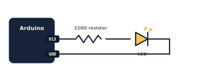
Electricity needs a complete loop to flow. Here's the classic first circuit — an LED with a resistor, which protects the LED.
Look at this diagram:
Now the code: an Arduino sketch has two parts — setup() runs once, loop() runs forever.
Type and run this in Tinkercad:
void setup() {
  pinMode(13, OUTPUT);      // pin 13 will power the LED
}

void loop() {
  digitalWrite(13, HIGH);   // LED ON
  delay(1000);              // wait 1000 ms = 1 second
  digitalWrite(13, LOW);    // LED OFF
  delay(1000);              // wait 1 second
}
⚠ Watch for the common bug: if the LED won't light, the circuit is usually not a complete loop, the resistor is missing, or the LED is backwards (LEDs only work one way). Check the loop first.
Ask yourself: "Which line turns the LED off, and what would happen if I deleted both delay lines?" (Answer: digitalWrite(13, LOW); with no delays it blinks too fast to see.)
Activity — Blink an LED
No hardware needed — you'll use the free simulator. Work through these steps on your own device.
- Open Tinkercad Circuits → Create new Circuit.
- Drag in an Arduino Uno, an LED, and a 220 Ω resistor. Wire: pin 13 → resistor → LED → GND.
- Click Code, switch to Text, paste the blink code above.
- Press Start Simulation. The LED blinks!
Watch out for a broken loop or a missing resistor — check that your loop is complete and the resistor is in the line.
⚠ If you finish early: change both
delay(1000)todelay(200)— what happens? Then make it blink an SOS pattern (3 short, 3 long, 3 short).
Check yourself
Try these — then check your answers:
- What are the three steps of physical computing? → Sense → Think → Act. Input → Arduino → output.
- What does
delay(1000)do? → Pauses for 1000 milliseconds = 1 second. - Which part runs forever —
setup()orloop()? →loop()repeats endlessly;setup()runs once at the start.
Wrap-up
- Explain Sense → Think → Act in one sentence using your blink circuit.
- Try this at home — Two-LED crossing: add a second LED on another pin and make the two blink alternately (like a level crossing). Screenshot the circuit for your portfolio and bring it to Session 8.
Tips & extra challenges
- Watch out: it's easy to think "the LED is broken." Usually the loop is incomplete, the resistor is missing, or the LED is inserted backwards — check those before assuming the part is faulty.
- Want more? Try this — the "light meter" mini-project: add a real input so your project can sense, and turn it into a small build with a goal. In Tinkercad, add a photoresistor (light sensor) to pin A0 (with its pull-down resistor to GND) and read it:
void setup() {
  pinMode(13, OUTPUT);
  Serial.begin(9600);        // so we can see the numbers
}

void loop() {
  int light = analogRead(A0);  // read the sensor (0–1023)
  Serial.println(light);       // print the value
  delay(200);
}
Run a proper little investigation: (1) open the Serial Monitor and record the reading for bright, dim, and covered — that's a tiny data table; (2) cover the sensor and watch the number fall in real time; (3) predict what number sits right between "lit" and "dark" — that becomes the threshold you'll use next session. Also want more? Keep the blink code running and print the light value each loop, so the board senses and acts at the same time. These readings are the "Sense" step — next session you add the "Think" (an if) to make an automatic night-light.
Vocabulary
| Term | Meaning |
|---|---|
| Arduino | A tiny programmable board |
| Circuit | A complete loop for electricity |
| Sensor | An input that senses the world |
| Output | Something the board controls (LED…) |
loop() |
Code that runs forever |
Resources
- Tinkercad Circuits — build & simulate Arduino, free, no hardware.
- Arduino — Built-in Blink tutorial — the official first project.
- Arduino Project Hub — thousands of project ideas.
Practice set
Practise on your own — extra tasks on Sense → Think → Act, circuits, and the blink sketch, easy to hard. Answers follow each arrow.
1. Name the loop. For a car's reversing beeper, name the Sense, the Think, and the Act. → Sense: distance sensor · Think: Arduino checks if something is close · Act: buzzer sounds.
2. Read the code. What does delay(500) do? → Pauses the program for 500 milliseconds = half a second.
3. Once or forever? Which function runs once, and which repeats endlessly? → setup() runs once at start; loop() repeats forever.
4. Slow it down. Change the blink sketch so the LED stays on for 2 seconds and off for half a second.
void loop() {
  digitalWrite(13, HIGH);
  delay(2000);            // on for 2 seconds
  digitalWrite(13, LOW);
  delay(500);             // off for half a second
}
5. Fix the circuit. A student wired pin 13 → LED → GND with no resistor and the LED burns out in the simulator. What's missing, and why? → A current-limiting resistor (≈220 Ω) in series — without it, too much current flows and the LED is damaged.
6. Second LED (build task). Add a second LED on pin 12 and make the two blink alternately (one on while the other is off).
void setup() {
  pinMode(13, OUTPUT);
  pinMode(12, OUTPUT);
}

void loop() {
  digitalWrite(13, HIGH);
  digitalWrite(12, LOW);
  delay(500);
  digitalWrite(13, LOW);
  digitalWrite(12, HIGH);
  delay(500);
}
7. SOS (harder sketch task). Make the LED blink S-O-S in Morse: three short, three long, three short, then a longer pause. → One clean way, using a helper for each flash:
void setup() { pinMode(13, OUTPUT); }

void flash(int ms) {
  digitalWrite(13, HIGH); delay(ms);
  digitalWrite(13, LOW);  delay(200);   // gap between flashes
}

void loop() {
  flash(200); flash(200); flash(200);   // S (three short)
  flash(600); flash(600); flash(600);   // O (three long)
  flash(200); flash(200); flash(200);   // S (three short)
  delay(1500);                          // pause before repeating
}
Going deeper (optional)
Optional — if you finish the blink early and want to know what's really happening.
Why the resistor, really — Ohm's Law in one line. Here's the number behind the 220 Ω. An LED wants only a small current or it fries. The Arduino pin gives 5 V; the LED itself uses about 2 V, leaving 3 V across the resistor. Ohm's Law says current = voltage ÷ resistance, so 3 V ÷ 220 Ω ≈ 0.014 A (about 14 mA) — a safe amount for an LED. The intuition, without heavy maths: bigger resistor → less current → dimmer, safer LED; too small a resistor → too much current → dead LED. Try a 1 kΩ resistor in the simulator and notice the LED gets dimmer.
delay() freezes everything. Here's why delay(1000) is a blunt tool: while the Arduino is "delaying," it can do nothing else — it can't read a button or a second sensor. Try adding a button and notice how presses get missed during a long delay. The professional fix uses millis() (checking the clock instead of freezing) — you don't need to code it yet, but knowing it exists explains why real projects rarely rely on long delays.
Common mistakes & fixes
- Mistake: No resistor between the pin and the LED. → Fix: Always put a current-limiting resistor (≈220 Ω) in series with the LED; without it the LED draws too much current and burns out.
- Mistake: LED inserted backwards. → Fix: LEDs are directional — the longer leg (anode) goes toward the positive/pin side, the short leg toward GND. Flip it if it won't light.
- Mistake: Forgetting
pinMode(13, OUTPUT);insetup(). → Fix: Declare every pin's mode insetup()before using it, ordigitalWritewon't reliably drive the LED. - Mistake: No connection to GND, so the circuit isn't a complete loop. → Fix: Trace the path pin → resistor → LED → GND; electricity needs a full loop back to ground to flow.
- Mistake: Deleting the
delay()lines and expecting to see a blink. → Fix: Keep a delay between ON and OFF — with none, the LED switches thousands of times a second and just looks dimly, steadily lit.
What's next
Session 8 — Build a Smart Gadget: the Unit 2 project — you'll combine a sensor, a decision, and an output into your own working invention.